
WoodMaxx WM-8H PTO Wood Chipper
Monday, November 30, 2015
Wednesday, November 18, 2015
Tuesday, November 10, 2015
Drive Line Safety Tips & Instructions
DRIVE LINE SAFETY TIPS
Agriculture and forestry are recognized as one of the most hazardous occupations. Today's farmer spends long hours in close proximity to increasingly and powerful machinery.
To avoid accidents, everyone from the component supplier and the company who manufacturers and assembles the machinery, to the dealers and ultimately the actual user, must keep safety in mind. The checklist below relates to the drive line of agricultural implements, general safety literature, and the standards published by the American Society of Agricultural Engineers.

DRIVE LINE SAFETY CHECKLIST
Drive-Line Specifications - The first step towards safe applications is to specify and test the drive-line so that it operates properly under expected field conditions.
- Specify and test the proper size joints and telescoping members based upon the power required by the implement, speed of rotation, joints, angles, shock loads, and expected life.
- Test the hitch geometry to prevent the drive line from:
- Extending beyond the recommended maximum length.
- Bottoming out.
- Reach a position that allows universal joints to lock.
- Exceeding the maximum allowable angle for constant velocity of the universal joints
Information concerning these par maters may be found in all drive-line manufacturer's catalogs.
3. Specify and test telescoping members to allow the lowest possible thrust loads, considering the expected working conditions.
4. Specify and test torque limiters to control excessive shock loads.
5. Where necessary, specify and test overrunning clutches to prevent inertial loads from overpowering the tractor.
DRIVE LINE SAFETY CHECKLIST
Hazard Reduction - The second step in specifying a safe drive-line application is to strive to eliminate as many hazards as possible.
- On drive-line with torque limiting or overrunning devices, specify that the device be positioned to the end of the drive-line by the implement.
- For implement connections which require bolts or set screws, select and/or supply hardware which minimizes protrusions. Information concerning these parameters may be found in all drive-line manufacturer's catalogs.
- For tractors PTO Shaft connections, specify a safety type yoke (twist or slide collar to minimize protrusions.
- Provide a proper clearance zone for the operation of the drive-line, to avoid damaging the shielding components.
Some common areas of interference are:
- Three point linkage.
- Extended or eye loop hitch pins.
- Hydraulic hoses.
Guarding - For hazards which cannot be eliminated effectively, guarding must be provided whenever feasible.
The PTO master shield, integral drive-line shield, and implement input connection shield should provide an interactive guarding system.
- Provide instructions by labels or manuals. The implement should be used only with the tractor's PTO master shield in place.
- Specify and test an integral drive-line shield with end cones which overlap, but not interfere with the PTO master shield or implement input connection shield.
- Provide an implement input connection shield to interact with the integral drive-line shield to provide guarding of the shaft coupling and any torque limiting devices installed on the drive line.
- Check that all routine maintenance of the drive-line can be done without removal on the shields.
Warnings and Instructions - Provide warnings and instructions for hazards associated with the machine. Provide instructions for proper maintenance and repair.
- Provide labels on the unit to advise the user of proper hitch dimensions and maximum safe operating speed.
- Check that proper danger labels are supplied with the drive-line concerning these par maters amy be found in all drive-line manufacturer's catalogs.
- Provide easy-to-understand instructions for proper drive-line concerning these parameters may be found in all drive-line manufacturer's catalogs.
- Advise against the use of PTO adapters which may defeat the purpose of the tractor's master shield and adversely affect the performance of the drive-line.
- Advise the user of locations of genuine original equipment spare parts.
Further information about drive-line specifications and safety may be obtained from your drive-line supplier and the following ASME standards and engineering practices:
S203 - Rear power take-off for agricultural tractors
S205 - Power take-off definitions and terminology for agricultural tractor
S207 - Operating requirements for tractors and power take-off driven equipment implements
S318 - Safety for agricultural equipment
S331 - Implement power take-off drive-line specifications
S333 - Agricultural tractor auxiliary power take-off drives
S350 - Safety alert symbol for agricultural equipment
S441 - Safety signs
S493 - Guarding for agricultural equipment
EP363 - Technical publications for agricultural equipment
Other standards may apply for particular types of implements. All drive-line manufacturers strive to produce a safe product. Drive-lines, like most other components must be used properly, including the use of proper tractor master shields and implement input connection shields. Please contact us if you have any questions about your drive-line applications.
Official Website: http://www.woodmaxx.com
Facebook Page: http://www.facebook.com/woodmaxx
Twitter Feed: http://www.twitter.com/woodmaxxltd
Tumblr Page: http://woodmaxxltd.tumblr.com/
Blog Spot: http://woodmaxxltd.blogspot.com/
WordPress Site: https://ptowoodchipperblog.wordpress.com/
LinkedIn Profile: https://www.linkedin.com/pub/woodmaxx-power-equipment-ltd/51/800/469
Phone # 1-855-966-3629
Email: woodmaxxltd@gmail.com
Address: 42 Jackson Street, Akron, NY, 14001
Hours of Operation: Monday through Friday 8am to 5pm Eastern Time
Thursday, November 5, 2015
Assembly Instructions for the WoodMaxx WM-8H PTO Wood Chipper
Assembly Instructions

Before you get started there are a few tools you will need:

Before you get started there are a few tools you will need:
- 13mm Wrench (same as 1/2 Inch )
- 16mm Wrench (same as 5/8 Inch )
- Adjustable Wrench
- 19mm Wrench or Socket ( same as 3/4 Inch )
Assembly Time 2.5 Hours
- Remove the plastic wrapping from the crate and inspect the chipper for any obvious shipping damage.
- Remove the unwrap all of the chipper components that are packaged with the crate.
- Remove the cardboard box from the in-feed bin; this box contains the users's manual, the hardware packet, extra shear bolts, and any additional items you may have purchased such as extra chipper knives.
- Open the hardware packet and organize the enclosed fasteners into separate piles.
- Remove the four bolts that secure the top of the crate frame.
- Located on the bottom of the crate is a cross bar that secures the chipper to the frame. Loosen the two bolts that hold this bar in place, and drive the bar forward with a dead blow hammer.
- Locate the lift point on the top of the chipper. This is the balance point, and the only point the chipper should be lifted from.
- Using a chain or strap that is rated strong enough to lift the wight of the chipper, and lift the chipper out of the crate.
- Measure the distance from the PTO spline of your tractor to the ground. Write down this measurement down you will need it for the next step.
- While the chipper is raised in the air, attach the four adjustable base legs so that when the chipper is on the ground, the spline of the chipper is slightly lower than the spline of your tractor. The shaft does not need to be perfectly horizontal, but it is recommended that the slope of the PTO shaft is no more than 15 degrees.
- Attach the skid shoe base using the included 8 carriage bolts, washers, and nuts. At this time, carefully lower the chipper to the ground, and remove the chain strap.
- Attach the left panel of the in-feed bin using two of the 2-hole straps and two M10x25mm blots. The straps will bend when tightened down. This panel can be identified by the two small holes on the bottom of the panel where the fasteners for the support leg attach.
- Attach the right side panel in the same manor. This panel can be identified by the four fastener holes in the middle of the panel where they hydraulic control valve mounts
- Attach the bottom panel of the in-feed bin, by first inserting the two M10x25 bolts through the side panels in the two holes closest to the feed roller. Do not tighten these bolts yet, and allow the panel to hang vertically.
- Raise the bottom panel in place and insert two M10x25 bolts through the side panel in the two holes closest to the end of the panel.
- Install the remaining four M10x25 bolts in the remaining four holes in the lower panel.
- Before tightening the bolts, ensure that the lower panel is slightly higher than the in-feed bin. This will prevent material from hanging up where the two pieces join together.
- Attach the top panel of the in-feed bin by installing the two M10x25mm bolts in the two forward holes of the panel.
- Install the two M10x40mm bolts in the two holes closest to the opening. These bolts should be installed from the inside so that they point outward. These bolts are used connect the safety bar in an upcoming step.
- Attach the support leg with two M10x25 bolts. Remember, the support leg should be in the down position during storage only. When the chipper is attached to the tractor, the support leg should be in the up position at all times.
- Attache the hydraulic control valve to the right side panel of the in-feed bin using four M8 lock nuts and four washers.
- Attach the upper feed roller assist lever using for M10x25mm bolts.
- Fasten the chain from the upper feed roller assembly to the feed roller assist lever. The hardware for this can be found by locating the end of the chain.
- Connect the safety bar to the two M10x40 bolts protruding from the top side of the in-feed bin. First, hook the control valve side of the safety bar over the bolt on the right side of the panel, then pull the opposite arm of the safety bar over the bolt on the left side panel.
- Thread an M10 lock nut onto the blot on either side, but do not tighten these nuts. this is a hing point, and the safety bar must move freely.
- Connect the safety bar to the hydraulic control valve by removing the lever on the valve, aligning the slot on the safety bar to the valve, and reinstalling the lever.
- Some hydraulic fittings are left slightly loose for shipping purposes, so at this time check and tighten the as needed.
- Affix the discharge chute to the chipper using four M10x15mm bolts along the four 10mm lock washer that were included in the hardware packet.
- Fill the hydraulic tank with 6-1/2 gallons of high quality hydraulic oil. Determine the viscosity recommended by looking on page 18 of the user Manuel.
- Connect the chipper to the 3 point hitch of your tractor, or if you have one, using your category 1 quick hitch.
- Next you must measure to determine the proper length of the PTO shaft.
- To do this, raise the chipper so that the spline of the chipper and that the spline of the tractor are horizontal with each other.
- Measure the distance from the end of the of the spline of the chipper. this is the measured shaft end distance, or MSED
- Now the shaft must be sized according to this measurement. Refer to the cart on the bottom of page 20 to determine if the shaft must be cut to size. If so, see the "PTO shaft cutting instructions on page 21.
- After properly sizing the shaft, locate the three grease fittings on the shafts U-joints, and pump several shots of high quality greast in the fittings. NOTE: Check to ensure that the zerk (grease) fittings are screwed in tight. Occasionally, dried paint may cover the end of the zerk fitting on the PTO shaft. Remove this by scraping the paint off with a knife prior to attempting to pump grease into these fittings.
- Attach the PTO shaft from the tractor to the chipper notice that one end of the shaft has a shear bolt, this end should be attached to the tractor.
- Prior to shipping the chipper to you, the following service has been done in our warehouse: the drive belts have been adjusted and tightened, the bearings on the chipper have been greased, USA made knives have been installed, adjusted, and the bolts were torqued to 40 ft. lbs.
- Before operating your chipper, you must fist purge any air from the hydraulic system.
- First locate the hydraulic flow control valve, this valve is used to increase and decrease the in-feed roller speed. The numbers 1-10 on the valve indicate the flow percentage 1=10% flow and graduates to 10-100% oil flow. The higher the flow the, faster the in-feed roller speed. At this time rotate the lever to #10 (full open) Note - use slower in-feed speeds to chip larger material. The ideal speed that your run material will vary depending on your tractors available HP and torque. This will require some trial and error on your part, but in a short time you will find the optimum in -feed speed for your tractor.
- The hydraulic control valve has three detent positions. the center position is neutral. Pull back on the lever toward the hopper opening to engage the feed rollers, and push forward on the lever to revers the feed rollers. At this time, leave the valve in the center position.
- Start your tractor's engine. While at idle, engage the power take off (PTO) of your tractor. Make sure that you are wearing protective safety gear at this time and that all bystanders are safely out the way.
- Slowly increase the engine speed of your tractor until the PTO speed reaches 540 RPMs. Usually there will be a mark on you tractor's tachometer that will indicate the necessary engine speed to achieve the required PTO speed of 540 RPM.
- Run the chipper with the hydraulic control valve in the center position for 2-3 minutes. Then move the lever into the remaining positions, and run it for and additional 2-3 minutes each. When you notice that the feed rollers change directions when the hydraulic valve is actuated, the system is purged. NOTE: Occasionally when purging the hydraulic system, air bubbles (foaming) will develop in the lines. This is evident when, immediately after purging the system, the rollers do not run smoothly. to rectify this, let the chipper sit overnight. This will allow the bubble to settle out of the hydraulic fluid.
- Disengage the tractor's power take off, and stop the engine. When the flywheel stops turning, recheck the hydraulic oil level. There should be a 1" air space at the top of the tank. If more oil is required, add it at this time!
- Setup is now complete. Please read and understand all operation instructions before using the chipper.
Wednesday, November 4, 2015
Set-Up Instructions for the WoodMaxx WM-8H PTO Wood Chipper
Set-Up Instructions:
Your chipper does need to be set up prior to installation. It arrives in a steel crate that can be dismantled in minutes. See assembly instructions the in-feed bin and discharge chute are shipped with the unit and are located in the bottom of the steel crate.

Visually inspect the in-feed bin, and the fly wheel before attaching to tractor, and applying power to ensure that nothing is in the chipper head. If the chipper deflector or any of the guards have been removed for shipping, be sure to replace them properly before use.
The PTO (Drive Line) is also shipped with the unit and is located in the bottom of the steel crate.

When mounting, keep the chipper as close to the tractor as possible.
Important - Make sure that the PTO shaft is sized properly.
While in use, keep the PTO shaft as straight as possible. No more than 15 degrees from level is acceptable.
Do not operate the chipper without the chip deflectors, and or drive belt cover properly in place.
Order Your WM-8H Today By Clicking The Link Below!
http://www.woodmaxx.com/WoodMaxx_8_PTO_Wood_Chipper_Hydraulic_Feed_p/wm-8h.htm
Website: www.woodmaxx.com
Facebook Page: http://www.facebook.com/woodmaxx
Twitter Feed: http://www.twitter.com/woodmaxxltd
Tumblr Page: http://woodmaxxltd.tumblr.com/
Blog Spot: http://woodmaxxltd.blogspot.com/
WordPress Site: https://ptowoodchipperblog.wordpress.com/
LinkedIn Profile: https://www.linkedin.com/pub/woodmaxx-power-equipment-ltd/51/800/469
Phone # 1-855-966-3629
Email: woodmaxxltd@gmail.com
Address: 42 Jackson Street, Akron, NY, 14001
Hours of Operation: Monday through Friday 8am to 5pm Eastern Time
#IndustrialChipper #PTOChipper #BestPTOChipper #BestPTOdrivenWoodChipper #WoodChipper #BestWoodChipper #PTOwoodChipperForSale #IndustrialWoodShredder #ChipperShredderMulcher #PTOhydraulicWoodChipper #IndustrialWoodShredder #CommercialWoodChipper #CommercialWoodChipperForSale #TractorMountedWoodChipper #TractorMountedWoodChipperForSale #WoodChipperPTO #CommericalWoodChipper #PTOdrivenWoodChipper
Tuesday, November 3, 2015
WoodMaxx WM-8H Hydraulic Wood Chipper Machine Operation
Remember to chip only clean material, or knife life will be shortened.
Do not move the chipper while the flywheel is turning.
Block the tractor wheels and set the parking brake while running the chipper.
Watch the discharge chute while operating the unit, and if the chips stop flowing, stop feeding material into the unit by pushing forward on the hydraulic control valve handle located on the side of the in-feed bin. This will stop the feed rollers from pulling material in.

Most of the time this will be enough to clear the chips out of the unit. If the unit slows down noticeably, first shut off the PTO power, then the tractor. Un-plug the flywheel by turning it backwards by hand with the discharge chute and the top section of the flywheel housing wrap off.

Remove the chips from the top of the head. If this fails, remove the clean-out door, located in the lower part of the front side-plate of the chipper below the main shaft, and then work the chips out of the case.
Replace the clean-out door after all the chips are removed, be sure to use both the lock washers and the flat washers.
Do not operate the chipper without the chip deflector in place.
Before stopping the chipper, be sure that all of the material is out of the chipper head and out of the in feed roller.
All of the material in the chute must be gone or the unit could jam on a small piece of material. This can usually be cleared by turning the unit backwards by hand.
Dull knives cause many problems such as: seeming lack of power, plugging of the discharge chute, rough cutting with more vibration than usual, feed roll shaft broken, main bearing house broken, main bearing working loose and the flywheel or knives hitting the case or bed knife, feed roller kicking out of gear, and not feeding.
When sharpening the knives, be careful to keep angle A at a 37-39 degree angle. Knives cannot be rounded, or the knives will not pull the material into the head.
The best way to tell if the knives need sharpening is to watch the chips coming out of the chip discharge. If they are long and straight, the knives are in need of service. Sometimes the knives feel sharp to the fingers, but may be worn or rounded. They will need to be sharpened.
Click the link below to view all of WoodMaxx PTO Wood Chippers!
http://www.woodmaxx.com/WoodMaxx_PTO_Wood_Chippers_s/12.htm
Click the link below to order your WM-8H Hydraulic PTO Driven Wood Chipper... Now only $2,799 http://www.woodmaxx.com/WoodMaxx_8_PTO_Wood_Chipper_Hydraulic_Feed_p/wm-8h.htm
Official Website: http://www.woodmaxx.com
Facebook Page: http://www.facebook.com/woodmaxx
Twitter Feed: http://www.twitter.com/woodmaxxltd
Tumblr Page: http://woodmaxxltd.tumblr.com/
Blog Spot: http://woodmaxxltd.blogspot.com/
WordPress Site: https://ptowoodchipperblog.wordpress.com/
LinkedIn Profile: https://www.linkedin.com/pub/woodmaxx-power-equipment-ltd/51/800/469
Phone # 1-855-966-3629
Email: woodmaxxltd@gmail.com
Address: 42 Jackson Street, Akron, NY, 14001
Hours of Operation: Monday through Friday 8am to 5pm Eastern Time
Do not move the chipper while the flywheel is turning.
Block the tractor wheels and set the parking brake while running the chipper.
Watch the discharge chute while operating the unit, and if the chips stop flowing, stop feeding material into the unit by pushing forward on the hydraulic control valve handle located on the side of the in-feed bin. This will stop the feed rollers from pulling material in.
Most of the time this will be enough to clear the chips out of the unit. If the unit slows down noticeably, first shut off the PTO power, then the tractor. Un-plug the flywheel by turning it backwards by hand with the discharge chute and the top section of the flywheel housing wrap off.

Remove the chips from the top of the head. If this fails, remove the clean-out door, located in the lower part of the front side-plate of the chipper below the main shaft, and then work the chips out of the case.
Replace the clean-out door after all the chips are removed, be sure to use both the lock washers and the flat washers.
Do not operate the chipper without the chip deflector in place.
Before stopping the chipper, be sure that all of the material is out of the chipper head and out of the in feed roller.
All of the material in the chute must be gone or the unit could jam on a small piece of material. This can usually be cleared by turning the unit backwards by hand.
Dull knives cause many problems such as: seeming lack of power, plugging of the discharge chute, rough cutting with more vibration than usual, feed roll shaft broken, main bearing house broken, main bearing working loose and the flywheel or knives hitting the case or bed knife, feed roller kicking out of gear, and not feeding.
When sharpening the knives, be careful to keep angle A at a 37-39 degree angle. Knives cannot be rounded, or the knives will not pull the material into the head.
The best way to tell if the knives need sharpening is to watch the chips coming out of the chip discharge. If they are long and straight, the knives are in need of service. Sometimes the knives feel sharp to the fingers, but may be worn or rounded. They will need to be sharpened.
Click the link below to view all of WoodMaxx PTO Wood Chippers!
http://www.woodmaxx.com/WoodMaxx_PTO_Wood_Chippers_s/12.htm
Click the link below to order your WM-8H Hydraulic PTO Driven Wood Chipper... Now only $2,799 http://www.woodmaxx.com/WoodMaxx_8_PTO_Wood_Chipper_Hydraulic_Feed_p/wm-8h.htm
Official Website: http://www.woodmaxx.com
Facebook Page: http://www.facebook.com/woodmaxx
Twitter Feed: http://www.twitter.com/woodmaxxltd
Tumblr Page: http://woodmaxxltd.tumblr.com/
Blog Spot: http://woodmaxxltd.blogspot.com/
WordPress Site: https://ptowoodchipperblog.wordpress.com/
LinkedIn Profile: https://www.linkedin.com/pub/woodmaxx-power-equipment-ltd/51/800/469
Phone # 1-855-966-3629
Email: woodmaxxltd@gmail.com
Address: 42 Jackson Street, Akron, NY, 14001
Hours of Operation: Monday through Friday 8am to 5pm Eastern Time
#IndustrialChipper #PTOChipper #BestPTOChipper #BestPTOdrivenWoodChipper #WoodChipper #BestWoodChipper #PTOwoodChipperForSale #IndustrialWoodShredder #ChipperShredderMulcher #PTOhydraulicWoodChipper #IndustrialWoodShredder #CommercialWoodChipper #CommercialWoodChipperForSale #TractorMountedWoodChipper #TractorMountedWoodChipperForSale #WoodChipperPTO #CommericalWoodChipper #PTOdrivenWoodChipper
Thursday, October 15, 2015
The WoodMaxx WM-8H PTO Hydraulic Wood Chipper
The WoodMaxx WM-8H PTO Hydraulic Wood Chipper

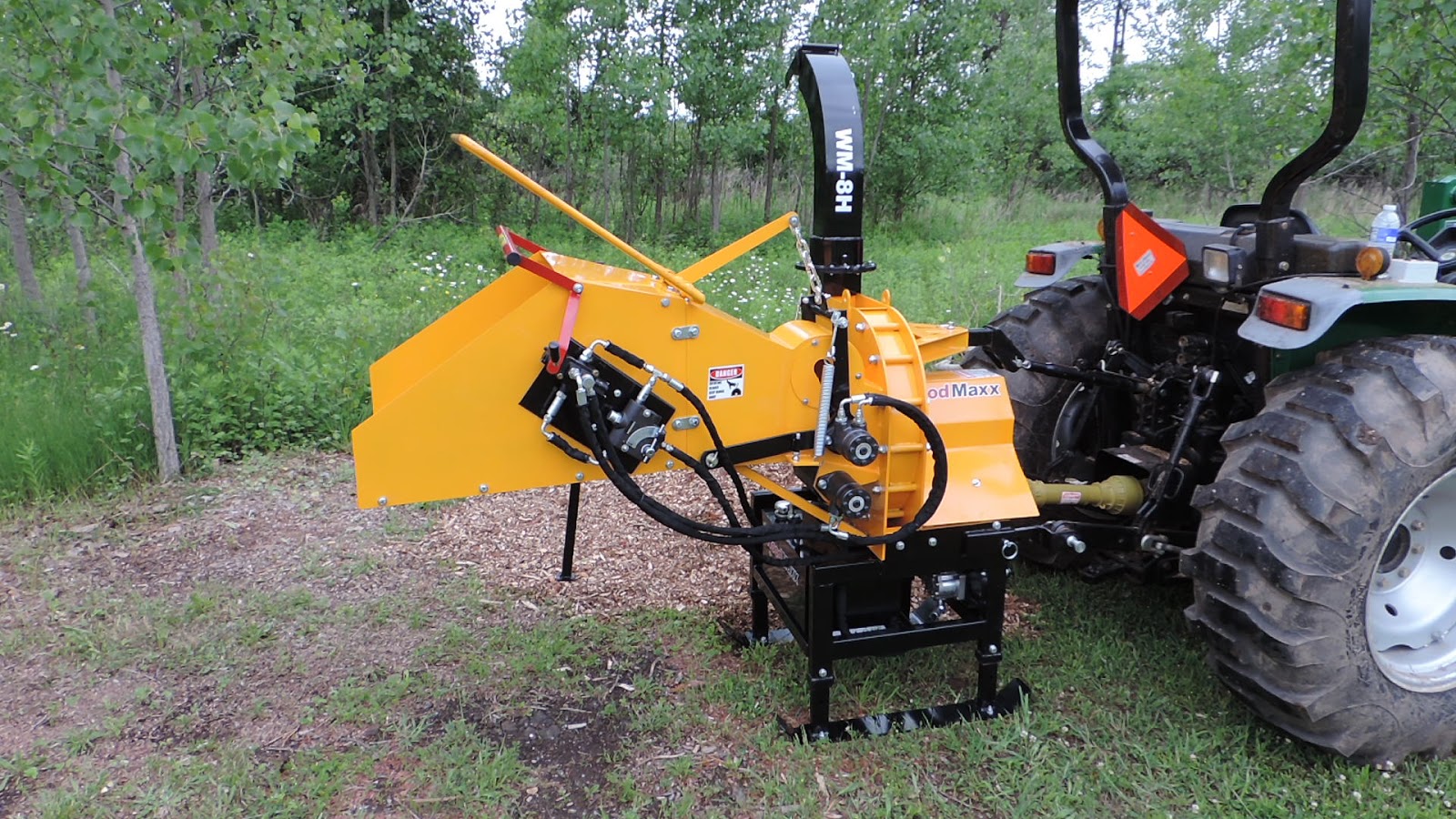
The WoodMaxx™ WM-8H hydraulic auto-feed chipper is a robust self-feeding PTO driven wood chipper attachment that mounts to the 3 point hitch of your tractor. This PTO wood chipper machine is compact, yet built to withstand commercial use. Dual powered in-feed rollers grab and pull material into the chipper head using two powerful hydraulic motors. These motors are powered by the chippers’ self-contained hydraulic pump and tank. High quality (A8 tool steel) made in the USA knives are standard equipment on all WM-series wood chippers.
The WoodMaxx™ WM-series chippers are so unique and innovative that they are now patent pending. Attempts have been made to copy this machine, but there is only one WoodMaxx™!
Click the link below to view all of WoodMaxx PTO Wood Chippers!
Subscribe to:
Posts (Atom)